Fan
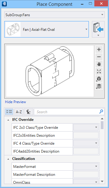
Selecting a fitting from the ribbon panel activates the Place Component settings dialog, where you can manage the schema parameters (DG instance properties). Also, the contextual Placement tab appears on the ribbon, that provides placement settings options for the currently selected fitting.
The generic placement settings, along with the unique set of dimensional and data parameters from the datagroup system provide the core workflow used to accurately position mechanical components within a system.
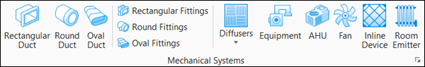
Component categories
Centrifugal fan is a mechanical device that moves air or other gases. It has a fan wheel composed of a number of fan blades, or ribs, mounted around a hub. The hub turns on a drive-shaft that passes through the fan housing. The gas enters from the side of the fan wheel, turns 90° and accelerates due to centrifugal force as it flows over the fan blades and exits the fan housing.
The axial-flow fans have blades that force air to move parallel to the shaft about which the blades rotate. Axial fans blow air across the axis of the fan, linearly, hence their name. This type of fan is usually used in cooling.
The fan device box gets placed at selected snap points along the duct. There are two types of fans – centrifugal and axial one each in three shape categories. The cell symbol represents the fan geometry. The placement takes the current property set in their common properties. The Chimney Caps inherit properties common to cap fittings.
Notable Properties
- Connection End Type – The end conditions of fittings are set to flange, male or female connections with full dimensional control by setting the End Type property. Also, the two ends are independent, and may have different connections. For example, the value fl-2;fe-.13 creates a flange at End1 with size 2, and a female connection at End2 with a clearance of .13.
- Cell Symbol Name – Sets model cell from cell library to the component by fitting cell proportionally to extents of device.
Notable Property Options
Auto Size – Opens the Auto Size Options dialog where the options allow to set the grille type, grille dimensions including the slots.
The list of fittings available in Fans group is compiled in the Fans types topic.